Whenever possible we should remove
all distinction between science education and �real� science.
Part 1: The Stiffness of a Toy Boat
 click images
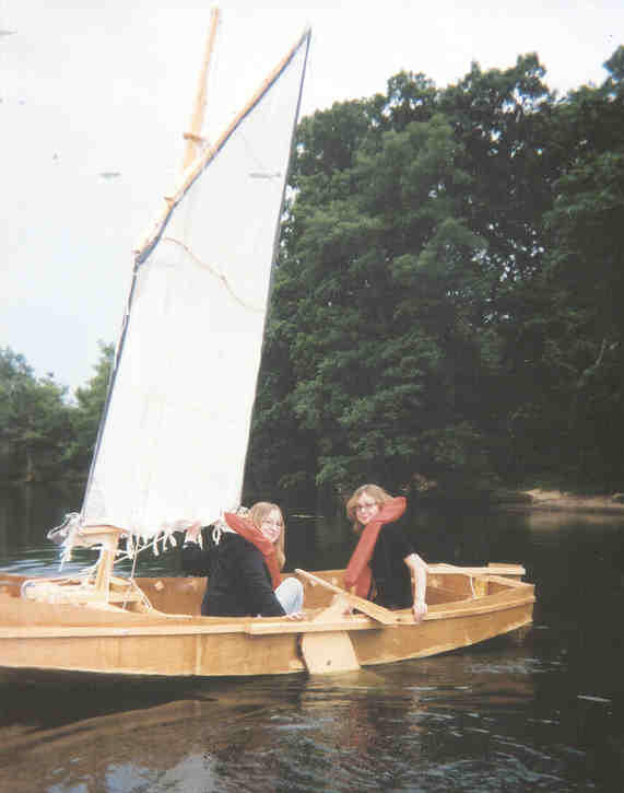
Above Left: City Lights -
reefed under light winds because these are novice sailors and because the nylon
sail had stretched. Right: Two successful models,
waterproof and constructed from discarded manila folders.
This is perhaps my best example of how
boatbuilding can combine the usefulness of science education with the
excitement of original research. First, I tasked a number of students with
finding a method for making waterproof toy boats �on the cheap�. Most were
college students, but a high school sophomore, his mother, and younger sister
also attended the evening boatbuilding effort that met one evening per week.
 click image
"every
wrong attempt discarded is often a step forward" ... Thomas Edison
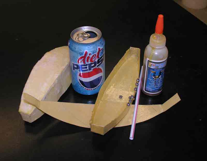
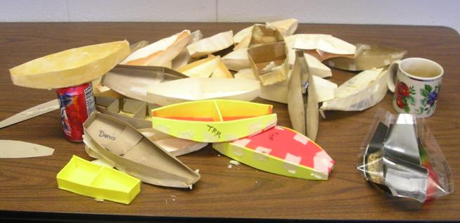
The first attempt used those ubiquitous
overhead transparencies that come with textbooks. That failure is shown just in
front of the coffee cup. One success, sitting one the soda can, was a manila
folder coated with paraffin wax. This idea was introduced by James, an elementary
education major with a strong interest in science. A student with initials TRR
proposed using foam sheets. But that was too expensive for my tastes. A number
of failures involved coating cardboard or manila folder paper with various
glues. We wanted very much to make a boat using school glue, but she always
became waterlogged and sank in a few hours.
For me the most useful way to construct a toy
boat appropriate for research is to cut panels out of manila folder paper and
coat her with waterproof polyurethane glue. Though not appropriate for middle
school children, polyurethane was the primary glue used to make City Lights,
the (real) boat shown at the top of this page.
If you inspect the boat in the lower right
corner of the first image, you will see the manila/polyurethane boat, along
with fishing weights and a straw. The fishing weights along one side were used
to vary the applied torque on the boat, causing her to tilt to one side. This
was suggested by the mother of the two pre-college children as she was watching
us struggle with a different scheme that used pennies we found in the lab. The
straw was her son�s idea as a way to measure the angle of tilt. (I think we
ended up using uncooked spaghetti.)
There was a reason I wanted all this done.
After reading various confusing and sometimes even conflicting explanations for
how water ballast stabilizes a sailboat, I decided to try my hand at
calculation. It is somewhat counterintuitive that water, which is neutrally
buoyant, could stabilize a sailboat. Though beyond the scope
of all my collaborators, the calculation shown below should be understandable
by any physics major. It predicts a linear relationship between applied
torque and angle of tilt, up to the point where the bottom corner leaves the
water. Hence the line in the graph terminates at this critical angle.
 �
�
The experimental data were taken by an adult
student, Debra, who had more manual dexterity than possessed by the pre-college
students. An excellent college algebra student, she lacked the background to
fully understand the theory. But we did have a lengthy discussion about whether
it was significant that her data did not seem to cross the origin. I think I
convinced Debra not to worry about it, and that the graph is an excellent match
to the data. Was I right? We need more investigation, perhaps with computer models,
to be sure.
Derivation
of the stiffness for a rectangular block with beam, B, and length, L:
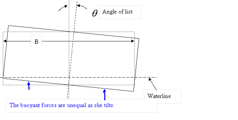
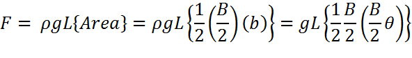
Begin with the left half
(where the boat rises).� By Archidemes
principle there is less buoyant force by an amount equal to the volume of the
triangle times the weight of the water it would take to fill that volume.� Taking B/2 to be the base of this triangle
and, b to be the height, the force equals:
Torque is the product of
force and lever arm, which is the distance from the centerline of the boat to
the center of the triangle.� But the
center of a triangle is 2/3 of the way the apex of the triangle to the midpoint
of the other side.� Hence the lever arm
is B/3.� There is an equal torque on the
other side (where the boat sinks) that also contributes.� Hence we multiply this force by 2B/3 to get a
net torque of:
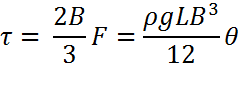
Note the strong dependence
on beam.� A boat with 10% more beam has
over 30% more stiffness.� Using calculus
we can get the same result by integrating the torque associated with the change
in pressure, P, at the bottom:
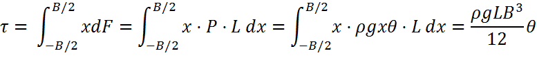
(Here we used the well-known
formula relating pressure to depth.)� Use
this result to create an integral over the beam as a function of length and use
Simpson�s rule:
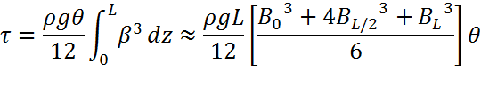
where the beam is evaluated
at the bow, the stern, and exactly at the middle.� If the boat comes to a point at the front, B0=0.